
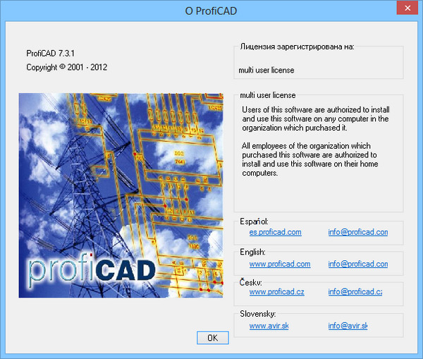
ProfiCAD 7.3.1
ProfiCAD – простое и удобное приложение для создания документации по электрическим схемам. Это профессиональный инструмент, который не требует специальных знаний.
Особенности программы:
- легкая в изучении и использовании - перетаскивайте символы на рисунок
- низкие системные требования - работает на любом ПК с Windows 2000 и выше
- поддержка Уникода - может использовать любой язык, любой технический символ
- база из 700 символов - новые символы могут быть легко созданы
- выдает таблицу соединений и ведомость материалов
- выдает список проводов
Изменения в версии 7.3.1 по сравнению с 6.2:
- Ability to remove redundant objects. New menu command File - Purge lets you remove unused objects (definitions of symbols and images) from the drawing and thus reduce the size of the drawing on the disc.
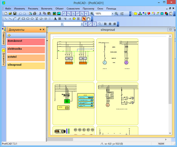
- Division of the symbols library. The program allows dividing the symbols library into several sets for easier work. You can switch between the sets using a drop down menu above groups of symbols (see picture). The new installations of the program have the library divided into three sets: "electronics", "electrical installations" and "others". You can divide your library in any other way as would suit you.
- How to divide the library
- Press key F12 – select Paths – press Open in Explorer
- Create several directories, which will serve as sets of symbols
- Drag groups of symbols into corresponding sets of symbols created in the previous step
- Enable display of the divided library: F12 – Symbols – "Divide symbols library"
- Restart ProfiCAD
- Improved export of drawings. Following the export of a drawing (in graphic formats or DXF), a dialog box will appear with a list of the output files. For multiple page drawings, a file will be created for each page of the drawing. You can preview the file by double clicking on the output file. When you click the Compress button, you can zip all the output files into one. The Open in Explorer button displays the output directory in Windows Explorer.
- Title block. Two new system variables are available for the title blocks: {_file} for the file name of the drawing, and {_path} for the full path of the drawing.
- Simpler drawing of lines and wires. If drawing a line or a link you draw a diversion and want to cancel it, press the backspace key.
- Enhanced fonts. Tab F12 - Fonts allows you to set your own font for cross-references. There is also a new option to set the color of the text for all types of labels in the drawings.
- Color fill of symbols. Some symbols can be color filled. This concerns symbols, which have closed areas, like circles, ellipses, rectangles, polygons, sections and slices of a circle. The fill color is set in the Properties panel or (if you want to color fill more symbols) using the command Object - fill color. The areas that have been colored in the editor of symbols, keep their original color. When filling a symbol with color, it may happen that some lines disappear, because they are covered by the colored area. In that case, open the symbol (right click on the mouse in the panel of symbols) and change the order of objects in the Explorer panel. Put the closed areas at the top of the list, so that they do not cover other objects.
- Adjustable format of the cross references. The format of the cross references can be adjusted by entering a formula in F12 - Symbols.
- Batch Printing. Use command File - Print Drawings to print multiple drawings at once. Use the "Setup" button to select a different printer. If you select a PDF converter as a printer, you can use this function for bulk export to the PDF format.
- Panel Documents. The new panel "Documents" allows you to preview documents without opening them. It works similarly to the Symbols panel- , just hover the mouse over a directory name. The panel shows documents from a directory (path) which is listed in the F12 - paths tab. The panel does not show documents that are located directly on the specified path. You need to create subgroups (directories) for each group of documents. For example, if the path to the documents is "D:\drawings\", you need to create several subdirectories, e. g. "D:\drawings\Project1\", "D:\drawings\Project2\" etc. and place your drawings into them. A document can be opened by clicking on the thumbnail of the document. A right-click menu appears with the item "to create a similar document." If you often create similar documents, you can create a document as a template and then create documents as a copy of the template.
- Labels of symbols have been renamed. Labels of symbols are now placed to the left of the symbols. If you prefer the old location to the right of the symbols, you can set this option in F12 - Symbols.
- Bill of material. The figure shows the new bill of material. When you check the "Group" checkbox, the number of pieces of each item is displayed.
- Multi-page documents. The new panel "Pages" allows you to create multipage documents. The icon of the panel represents a drawing in a spiral binding. Each page has a short name (recommended length is 4 characters) that appears in the panel "Pages" and cross references. If a title block is enabled, it is displayed on all pages.
- Printing. The previous version of the program tried to utilize the printable area of printers to the maximum. Only very thin margins remained around the drawing. The new version allows you to set the preferred page margins. The page margins can be set in F12 - Document - Size. The recommended value is 10 mm. In order to fit the drawings created in previous versions into an area decreased by the page margins, the drawing is automatically scaled down. In such cases the option F12 - Document - Size - "include page margins in the drawing area" is not checked.
- Cross references - wires. If two wires have the same name, they are considered to be connected (they have the same potential). The name of a wire can be entered in the "Properties" panel. If a wire ends in the air and there is another wire with the same name on another page, the reference to the other wire is automatically displayed.
- Cross references - symbols. A component is an electrical device that consists of one or more symbols. For example, a relay coil and contacts. The main symbol is the relay coil; the individual contacts are subordinate symbols.
- Parameterized symbols. This symbol (pulse-code modulation) can be used only with values 3 and 7. Open the symbol in the editor of symbols. Replace the values 3 and 7 by parameters - for example x and y in curly braces { }. You will get a parameterized symbol. In the drawing select the symbol, open the Properties panel (by double clicking the symbol), click the "Parameters" link and enter the values for the x and y parameters.
ОС: Windows XP, Vista, 7, 8 (32-bit / 64-bit).
Скачать программу ProfiCAD 7.3.1 (8,1 МБ):

-A.L.E.X.- 24/12/12 Просмотров: 2985
0
Отсутствует файл dll просто не запомнил какой точно программа не может быть запущена, и патч сильно больно стремный, только открыл архиватор как BitDefender IS его и грохнул без предупреждения и пошел комп в перезагрузку, и с под DOS пошла очистка ноута.
кошмар, прям тотальный коллапс
F12
Ostatni->Jasykove prostredi(поставить русский)
как сделать русским, а не чешским